MVDDS in depth
Historically a large spectrum was assigned for satellite communications, most notably for fixed and Direct Broadcast Satellites (DBS) service in Ku-band. From a transmission point of view, data is transmitted in a similar fashion as the terrestrial television broadcasting method but MVDDS systems occupy a higher frequency range. MVDDS systems occupy 10.7-12.7 GHz internationally and 12.2-12.5 GHz in USA. So a large radio frequency bandwidth of 500, 1,000 or even 2,000 MHz is available for MVDDS usage. The picture below (Picture 1 ) shows the bandwidth ratios available in different frequency bands for broadband.
(Illustration #1)
RSAccess has and continues to develop numerous point-to-multipoint applications using the MVDDS frequency and related technology.
There are many manufacturers worldwide that offer a broad variety of inexpensive parts and hardware addressed to this frequency band.
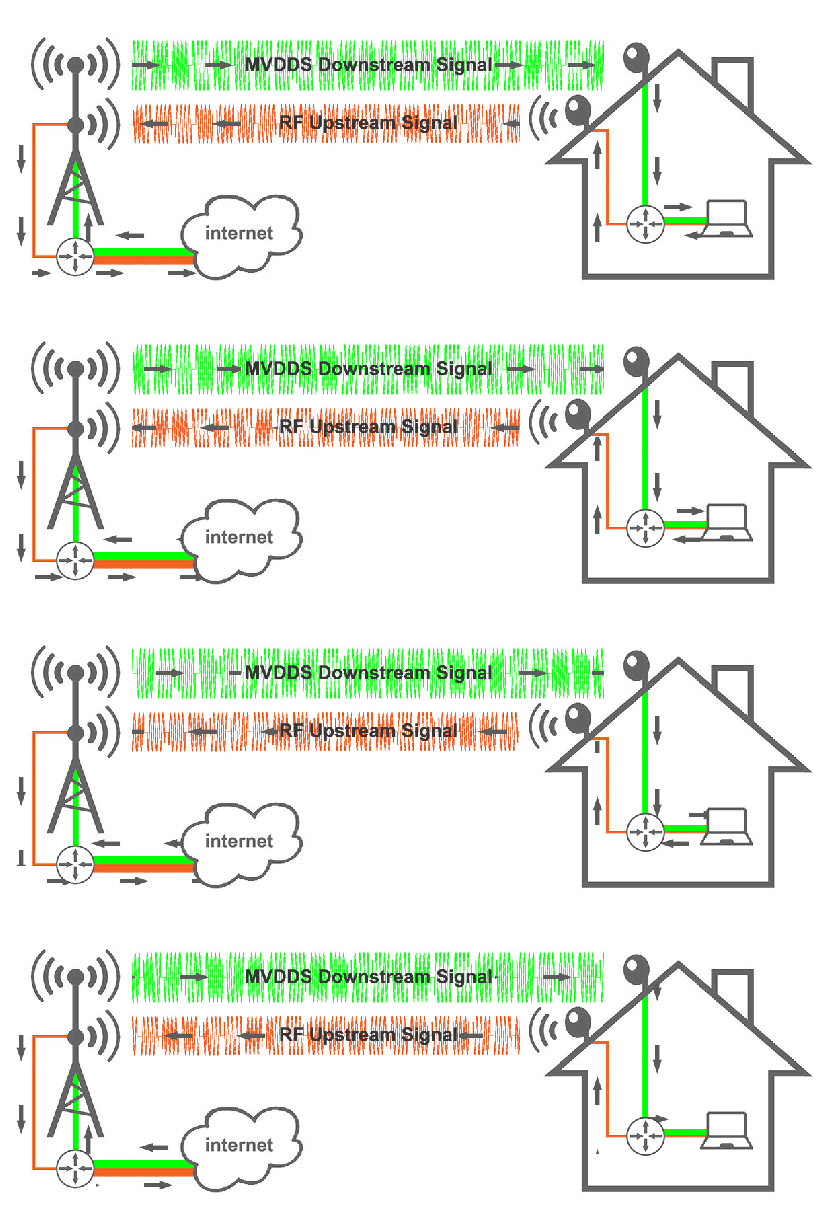
The below picture shows the general idea behind an MDSA MVDDS system in Internet access application in a point-to-multipoint downstream configuration. The “MVDDS Downstream Signal” delivers encapsulated IP DATA to a customer equipment. The “RF Upstream Signal” brings back to the main tower the encapsulated IP DATA from the customer equipment. This is one of RSAccess' several point-to-multipoint use cases.


In a real installation the RF Upstream is two-way link for return path. The animated picture shows the upstream and downstream customer data separation in the System only.
The MVDSS Radio Server is at the main TX site. The server consists of a number of components that carry out various functions ranging from IP encryption to authentication. It is a turnkey system; no extra equipment is needed to provide high-speed internet access. At the subscriber end, an MDSA MVDDS modem is used with the Ethernet Router which plays an important role separating downstream and upstream traffic between MVDDS and uplink spectrum. End user equipment will typically have multiple interfaces: a MVDDS antenna interface, an Ethernet interface, and an interface for the upstream transmission. The equipment receives an IP address (dynamic or static) from our NOC. This upstream connection can be achieved using many different methods to include WiMAX, Wi-Fi, WLL, PSTN etc. MDSA designs and installs an upstream connection based on customer needs, topology, and available spectrum allocation. The downlink connection is provided via the high-speed MDSA MVDDS system for Internet data and IPTV data. The MVDDS system is able to achieve a “to the home” download speed exceeding 50, 60, even 85 Mbit/s for each customer.
As the operator needs more downstream data, or to serve more customers, they only need to add additional MVDDS transponders (TR2, TR3) to the system.

From a coverage point of view, more MVDDS layers can be added to the system to downstream data. In this case each transponder operates on its frequency. Transponder 1 has its central frequency and takes its own bandwidth, Transponder 2 has another central frequency etc.


In addition each transponder may produce different modulations- QPSK, 8PSK, 16APSK to achieve a max data speed, depending on the distance (signal strength) from the transmitter.
An MVDDS transponder, for example, using 16APSK modulation has a very high data rate but can only be used across a short distance. The QPSK transponder brings a higher coverage area, maximizing service area but at the cost of a lower data rate.
An MVDDS system can be designed for or its configuration can be changed during operation to suit business needs. When paired with a WiMAX or LTE upstream channel, the MVDDS system provides Cable-class speeds to many users in a given geographical area in the shortest time possible.
